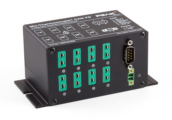
PCAN MU-Thermocouple1 CAN FD
Configurable System for Data Acquisition and Data Processing
The MU-Thermocouple1 CAN FD captures, processes, and transmits data via CAN FD. The temperature is measured via 8 connectors, which are specified for the temperature ranges J, K or T, depending on the product version. Temperatures can be captured in Celsius, Fahrenheit, or Kelvin and processed with an individual scale and offset. The measurement data is then transmitted via CAN FD or classic CAN.
Data processing, message transmission, and LED display are set up with the free Windows software Thermocouple FD Configuration. The configuration created on the computer is transferred via the CAN bus to the MU-Thermocouple1 CAN FD which then runs as an independent CAN node. Multiple devices can be configured independently on a CAN bus. (Requires a PEAK CAN interface.)
Scope of supply
- MU-Thermocouple1 CAN FD in aluminum casing
- Mating connector for voltage supply
- Configuration software Thermocouple FD Configuration for Windows® 10 (32/64-bit) (Configuration requires a PEAK CAN interface
- Manual in PDF format
- Note: Thermocouple probes are not included
- 8 Mini sockets for thermocouple types J, K, and T (depending on the assembly of measuring modules at delivery)
- 4 galvanically isolated measuring modules, each with 2 thermocouple sockets of the same type
- Measuring ranges:
- J: -210 to +1121 °C
- K: -200 to +1370 °C
- T: -200 to +400 °C
- Measurement accuracy: 0.2 %
- Accuracy of the reference sensors: typically ±0.5 K, max. ±1.0 K at +25 °C ambient temperature
- Resolution for temperature data at CAN communication: 1/16 °C
- High-speed CAN connection (ISO 11898-2) for data transfer and configuring,
galvanic isolation up to 500 V - Basic configuration with the Windows® software Thermocouple Configuration
- Advanced configuration with the Windows® software PPCAN-Editor 2
- Pre-processing of readings possible with integrated microcontroller
- Aluminum casing with flange. DIN rail fixing option available on request
- Voltage supply from 6 to 34 V
- Extended operating temperature range from -40 to 85 °C (-40 to 185 °F)
| Power Supply | Supply voltage: Nominal 12 V DC (6 - 34 V possible) Current consumption: ca. 100 mA at 12 V |
|---|---|
| Measuring modules | Count: 4 Connectors: 2 Mini sockets for thermocouples (DIN EN 50212) per module, 8 altogether Galvanic isolation: each measuring module internally against the supply voltage, up to 500 V Supported thermocouple types (IEC 60584-1): J (-210 - +1121 °C); K (-200 - +1370 °C); T (-200 - +400 °C); (according to the used module) Measurement accuracy for thermocouple inputs: ±0.2 % Influence of ambient temperature: 10.5 ppm/K Reference sensors: 4 (1 per measuring module) Accuracy of the reference sensors: ±1 K at 0 - +70 °C; ±2 K at -20 - +85 °C; ±3 K at -40 - +125 °C Measuring category: CAT I (only electric circuits that are not connected to the mains) |
| Controller module | Microcontroller: NXP LPC2366 Resolution for temperature data at CAN communication: 1/16 °C Sampling rate of the sensors: 3 Hz |
| CAN | Specification: ISO 11898-2, High-speed CAN 2.0A (standard format) and 2.0B (extended format) Bit rates: 40 kbit/s - 1 Mbit/s; Lower bit rates on request Transceiver: NXP TJA1040T Connection: D-Sub (m), 9-pin, assignment according to specification CiA® 102; Optional 5-Volt supply at pin 1 for external devices (e.g. bus converters), max. 100 mA; Galvanic isolation up to 500 V Termination: none |
| Dimensions | 130 x 60 x 73 mm (W x H x D) (incl. mounting plate and connectors) See also dimension drawings in Appendix B in the User's Manual |
| Weight | 420 g |
| Operating temperature | -40 - +85 °C (-40 - +185 °F) |
| Storage temperature | -40 - +100 °C (-40 - +212 °F) |
| Relative humidity | 15% to 90% (non-condensing) |
| Ingress protection (IEC 60529) | IP20 |
| EMC | DIN EN 61326-1; EC directive 2004/108/EG |
| Safety | EN 61010-1 + Amendments 1 and 2 |
| MU-Thermocouple1 CAN manual |
| User's Guide in English |
| PPCAN-Editor 2 |
| Configuration software for Windows® 10, 8.1, 7 (32/64-bit) |
