


- Data conversion between CAN, CAN FD and LIN buses
- One CAN channel
- One optional CAN FD channel
- One LIN channel
- SAE J1939 support
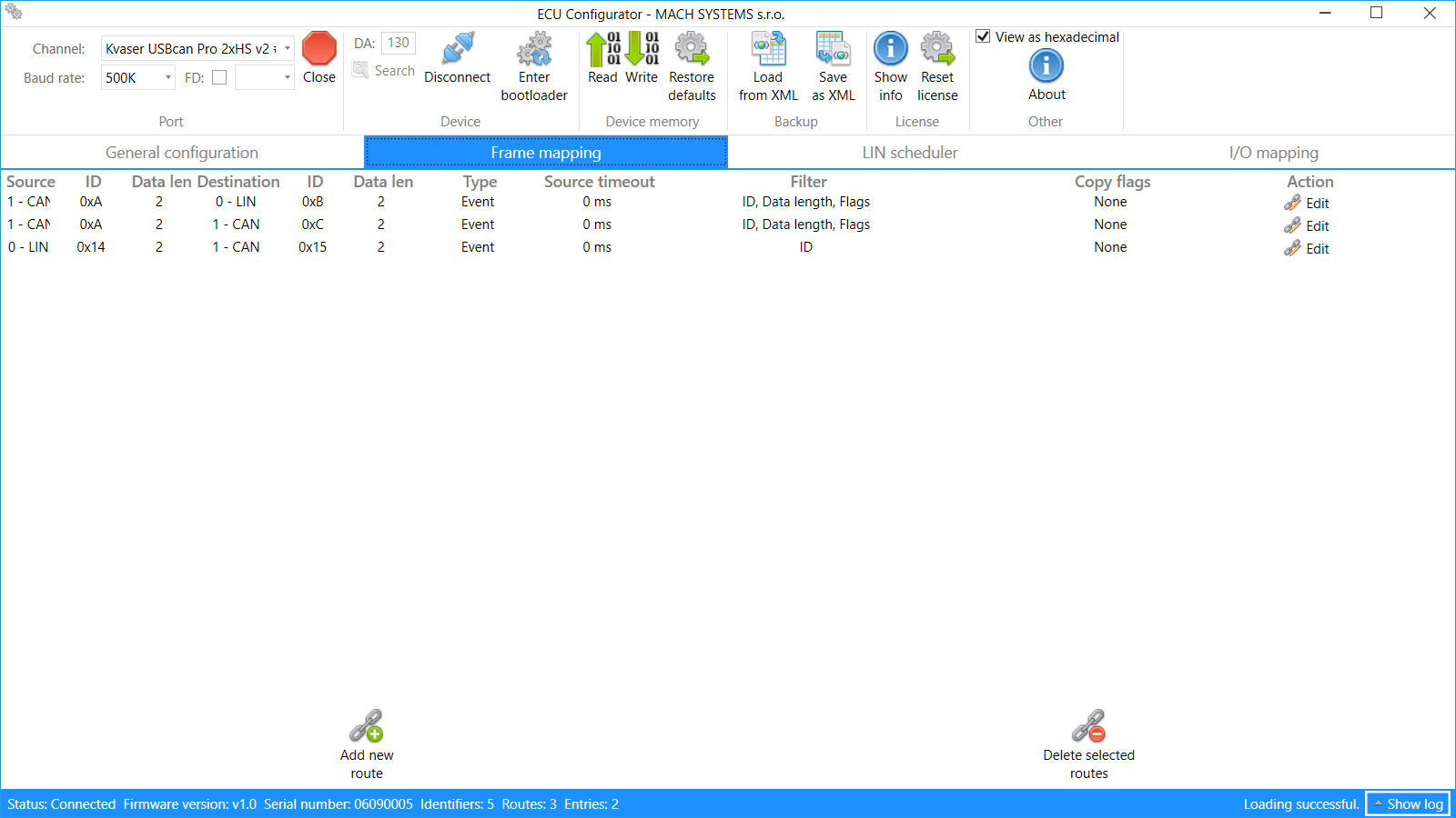
- Configurable frame and data routing between channels
- Up to seven multi-purpose inputs and outputs with current measurement
- Configurable I/O mapping onto CAN or LIN frame data
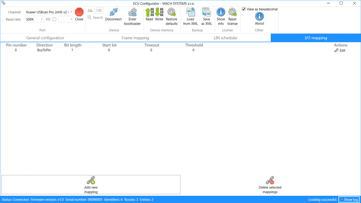
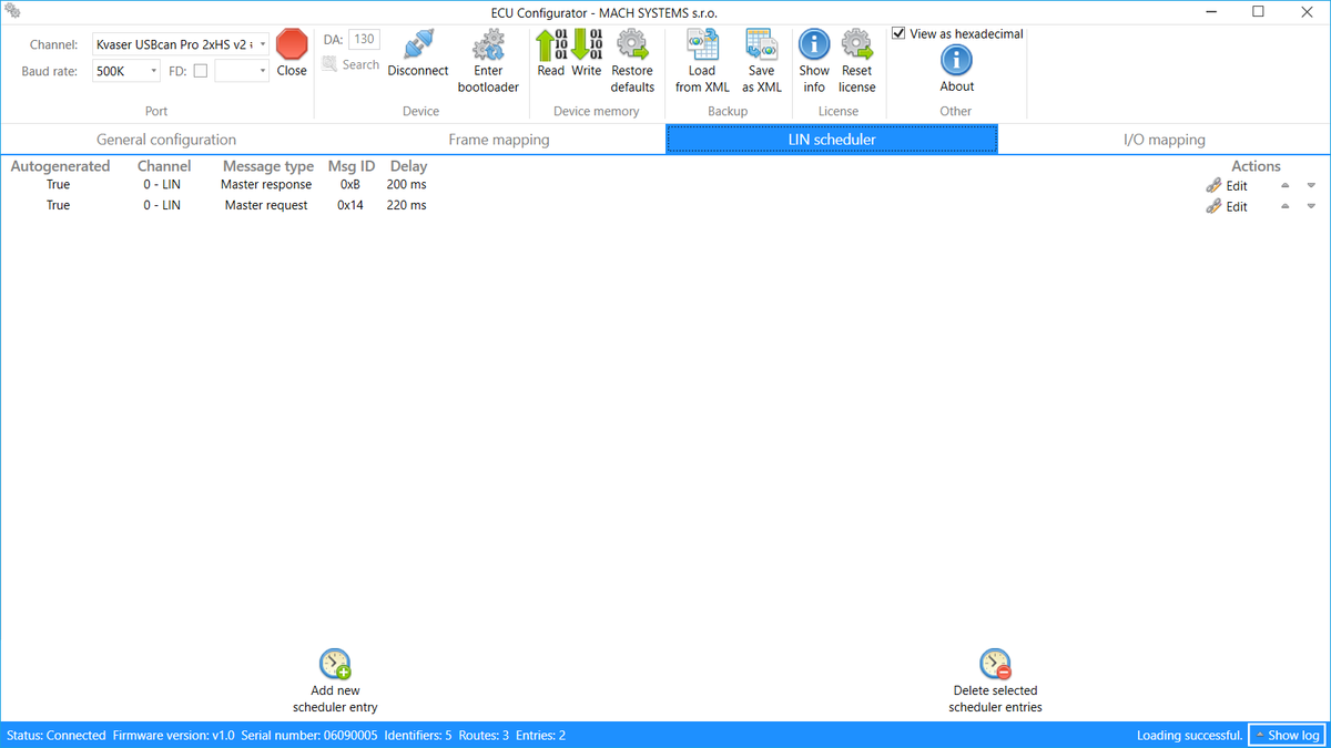
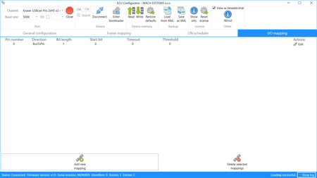
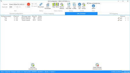
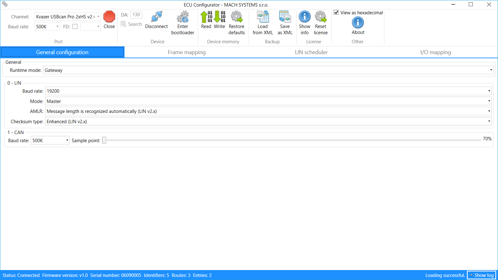
- PC tool for easy configuration
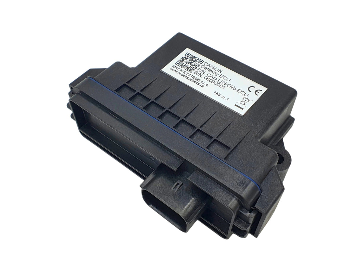
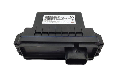
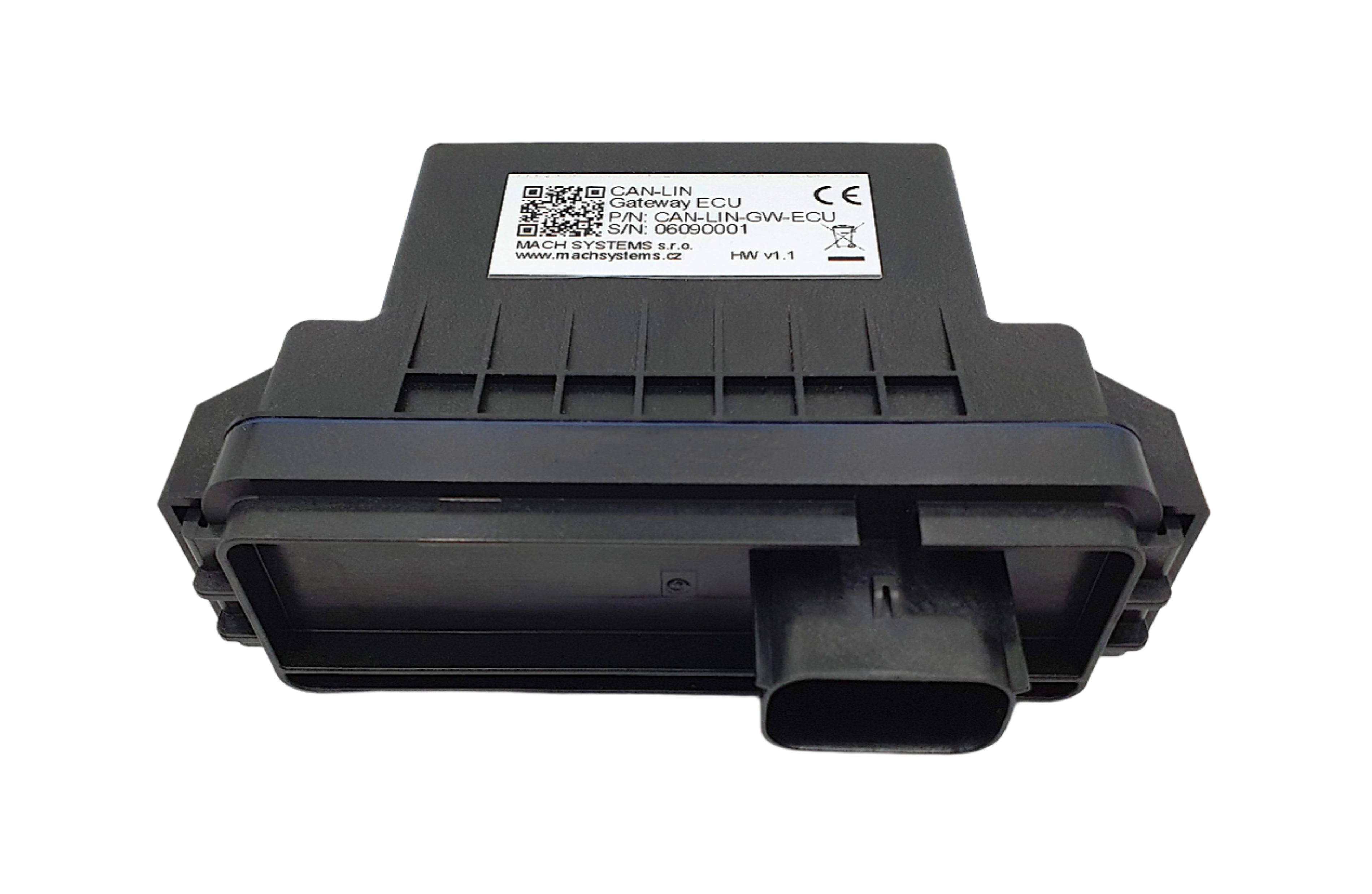
- Waterproof automotive-grade ECU
- Suitable for 12 V and 24 V systems
- ECE-R10 (E1) approval (planned for 2021/Q4)
- Customization on request
Usage Examples:
- CAN-LIN bridge
- CAN – CAN FD gateway
- Remote I/O ECU
- Universal SAE J1939 ECU
| Property | Value |
|---|---|
| The information herein is subject to change without notice. | |
| Communication Channels | |
| CAN | CAN 2.0B (baud rates: 125 / 250 / 500 / 1000 KBaud) Wake-up capable Bus termination: optional (see Ordering Information) |
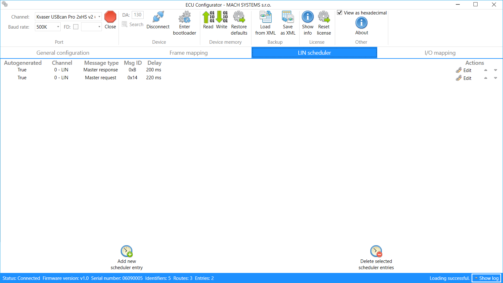
| LIN | LIN v2.2a – ISO 17987 (baud rates: 9600 / 10417 (SAE J2602), 19200 Baud), supports both Master and Slave, and Classic/Enhanced checksums. User-configurable LIN Master’s scheduler |
| CAN FD | ISO CAN FD (baud rate up to 8 MBaud): optional Bus termination: optional see Ordering Information |
| CAN Bus Protocols | SAE J1939, Raw CAN |
| Inputs and Outputs | |
| Number of channels | 4 – 7 (see Ordering Information) |
| Channel mode | Configurable: Analogue/digital input, HSD output |
| Analogue inputs | 0 – 30 V, 12-bit ADC, sample rate 10ms |
| Digital inputs | Configurable voltage threshold HSD with short-circuit protection and current measurement. |
| Digital outputs | PWM capable Max. current 1.5 A per channel (2 A in total for IO1-4 and IO5-IO7) |
| Mapping | Inputs and outputs can be mapped onto LIN and CAN frame data byte |
| Electrical and Mechanical | |
| Input voltage | 7 – 30 V DC |
| Power consumption | Operation: 0.04 A @ 12 V (+20 °C) Sleep: 40 µA @ 12 V (+20 °C) |
| Power management | Options: Automatic wake-up and sleep based on CAN bus activity KL15 (Ignition switch) signal |
| MCU | 16-bit Automotive DSP |
| Firmware | Firmware update over CAN bus |
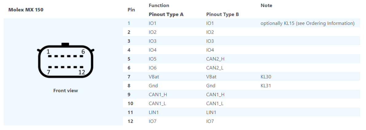
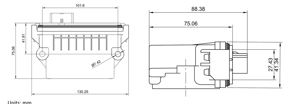
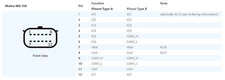
| Connector | 12-pin Molex MX150 Mating connector: Molex 33472-1201 (p/n: GW-ECU-CONNECTOR-12p) |
| Dimensions (L x W x H) | 130 x 75 x 43 mm (5.12” x 2.95” x 1.69” in) |
| Weight | 175 g (0.386 lb.) |
| Operating temperature | -40 to 85 °C (-40 to 185 °F) |
| Ingress Protection | IP67 |
| Certifications and Tests | |
| Road vehicles | ECE-R10 (E1) approval (planned for 2021/Q4) |
| Transient pulses | ISO 7637-2 |
| EMC | CISPR 25 |
| ESD | EN 61000-4-2 |
| Vibrations | EN 60068-2-27 EN 60068-2-64 |
| User Configuration | |
| ECU modes |
Communication gateway: Configurable bi-directional frame mapping between CAN and LIN channels, digital and analogue inputs and outputs mappable onto CAN or LIN data frames. SAE J1939: ECU’s inputs and outputs are available over PGNs. Dynamic addressing and DM1 supported. |
| Communication channel parameters | CAN and CAN FD: Baud rate, sample point LIN: Baud rate, Checksum type, Master/Slave, scheduling table for LIN Master |
| Configuration | User’s configuration is stored in the ECU’s non-volatile memory. |
| PC application | ECU Configurator Tool (p/n: GW-ECU-CONFIG-TOOL) is a Windows application that allows to easily configure the ECU over CAN bus. |
| Data Sheet |
| CAN-LIN Gateway ECU Data Sheet in PDF Format |