


- Freely programmable
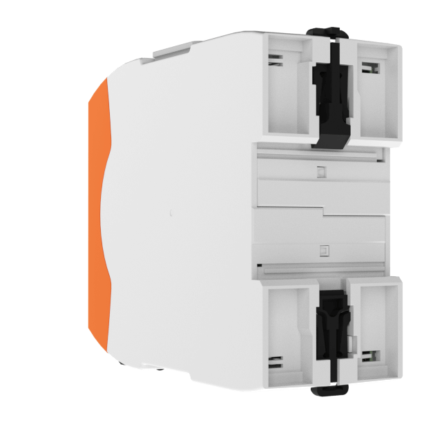
- Modular and expandable design
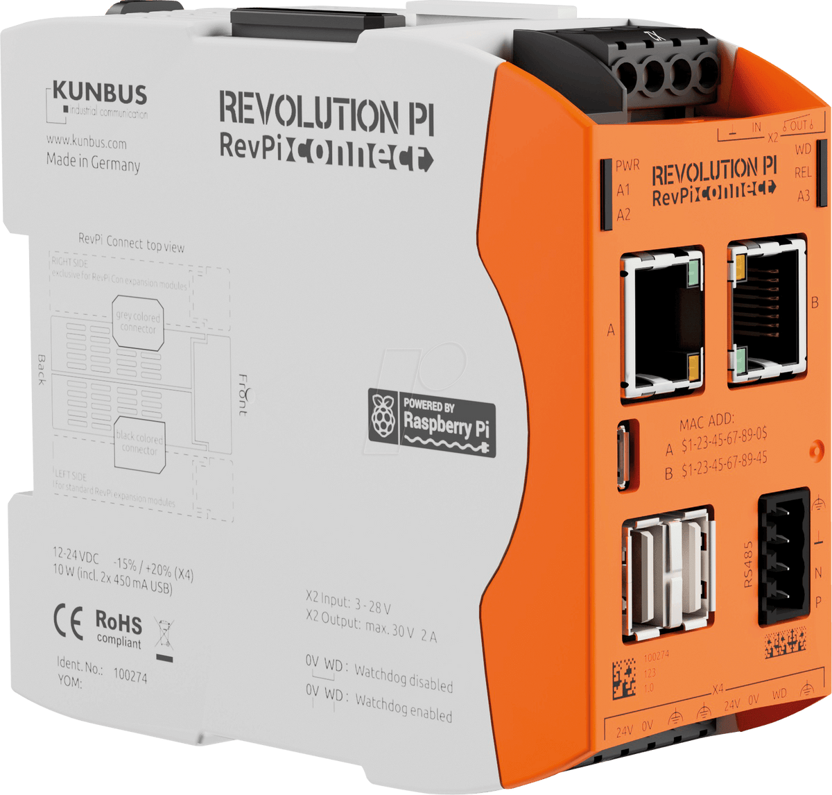
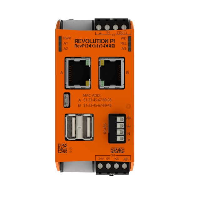
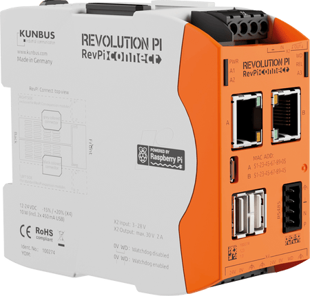
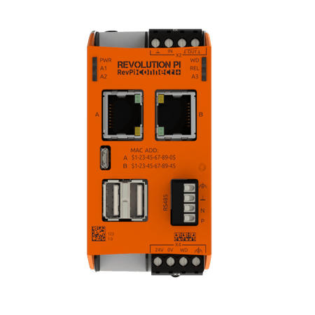
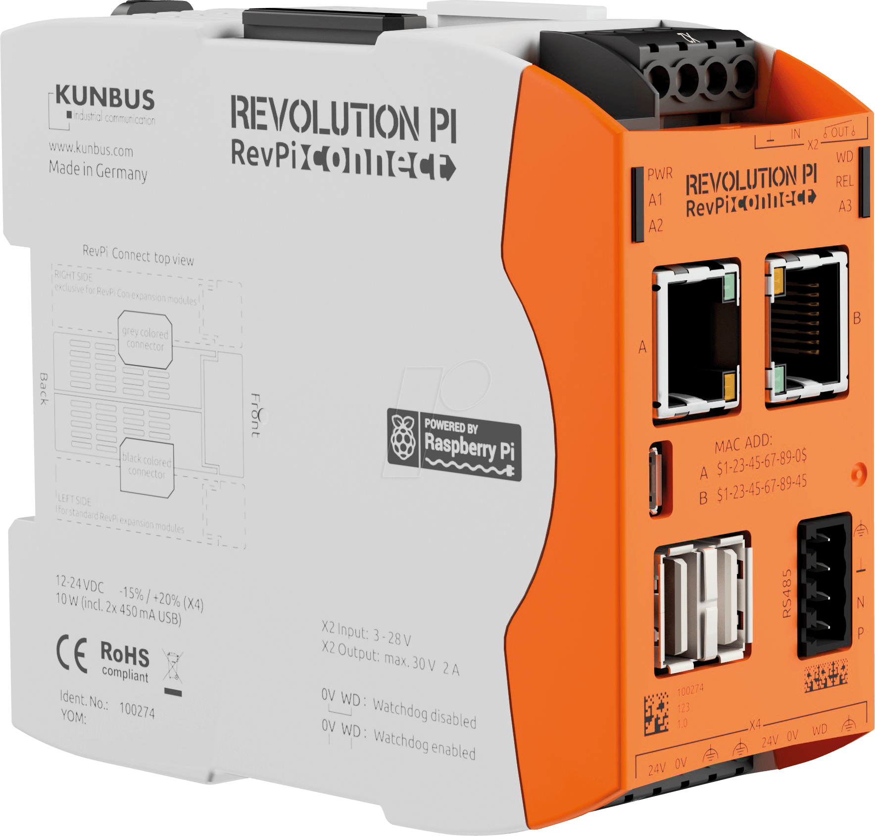
- Two Ethernet ports
- RS485 screw terminal
- Hardware watchdog
- Supports all major industrial network protocols
- OPC UA & MQTT
- Node-RED
- Python
| Housing dimensions (H x W x D) | 96 x 45 x 110.5 mm |
| Housing type | DIN rail housing (for DIN rail version EN 50022) |
| Housing material | Polycarbonate |
| Weight | approx. 197 g / 224 g (incl. connectors) |
| IP Code | IP20 |
| Power supply | 12-24 V DC -15%-/ +20% |
| Max. power consumption | 20 Watt (incl. 1 A total USB output current) 1 |
| Operating temperature | -40 °C....+55 °C2 |
| Storage temperature | -40 °C....+85 °C |
| Humidity (at 40°C) | 93% (non-condensing) |
| Interfaces | 2 x USB A (Total current draw from both sockets max. 1 A) 3 2 x RJ45 10/100 Ethernet (using separate MAC addresses) 1 x RS485 screw-type terminal (not galvanically isolated) 1 x Micro-USB (solely for image transfer to eMMC) 1 x Micro HDMI 1 x PiBridge system bus 1 x ConBridge system bus |
| Connectors | 1 x 4-pole screw-type terminal for relay contact and signal input 1 x 8-pole spring clamp connector for power supply |
| Processor | Broadcom BCM2837 quad-core ARM Cortex A53 (ARMv8) |
| Clock rate | 1.2 GHz 2 |
| Processor cooling | Passive with heat sink |
| RAM | 1 GByte |
| Flash memory | 4 GByte |
| Number of digital input channels | 1 |
| Input type | 24 V control voltage (e.g. for power-good signal of a UPS) |
| Input thresholds | approx. 3.0V (0 -> 1) / 2.3V (1 -> 0) |
| Input protection | against overvoltage, negative voltages |
| Number of digital output channels | 1 |
| Output type | Relay contact, approval up to 30 V switching voltage (e.g. for power supply of a router) |
| Maximum current load of the contact | 2A @ 30V DC (resistive load!) |
| Software integration of input and output | Via GPIOs and process image. Output is optionally switched by hardware watchdog |
| Hardware watchdog functionality | Can be disabled by bridging the 8-pin connector. Reset by toggling a GPIO or alternatively a bit in the process image |
| Hardware watchdog interval | Trigger after approx. 60 seconds without toggling the reset bit |
| Compatible modules for system expansion | All RevPi IO modules and RevPi Gate modules can be connected via the PiBridge system bus. Various transceiver modules can be connected via the ConBridge system bus. |
| Protection of the power supply inputs | Reverse polarity protected, overvoltage protection |
| ESD protection | 4 kV / 8 kV (according to EN61131-2 and IEC 61000-6-2) |
| EMI tests | Passed (according to EN61131-2 and IEC 61000-6-2) |
| Surge/Burst tests | Passed (according to EN61131-2 and IEC 61000-6-2) |
| Buffer time RTC | min. 24 h |
| Optical indicator | 6 status LEDs (bi-color), two of them freely programmable |
| RoHS conformity | Yes |
| CE conformity | Yes |
| Tutorials |
| RevPi Connect+ Tutorials |
| Technical Data Sheet |
| RevPi Connect+ Technical Data Sheet |
| Flyer |
| RevPi Connect Flyer |
| Release Notes |
| Release Notes for Buster March 2021 |
| Buster Image File |
| Image file for installing RevPi Buster |