


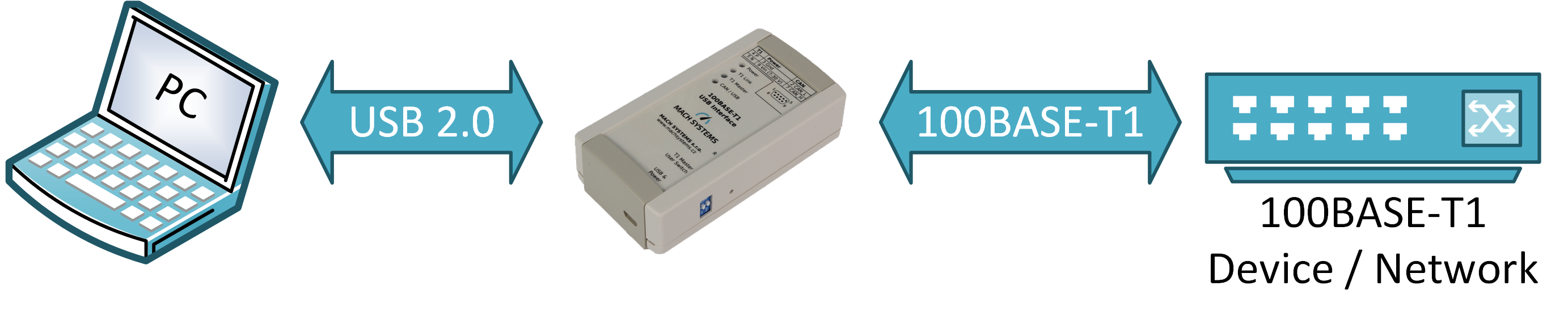
Converter acts as an Ethernet network interface card when plugged into an USB port.
The 100BASE-T1 USB Interface (Media Converter) connects a 100BASE-T1 network to any computer with an USB port. The interface easily connects Automotive Ethernet devices with OPEN Alliance BroadR-Reach (OABR) port, such as cameras or ECUs, directly to any PC without a need of an on-board network card.
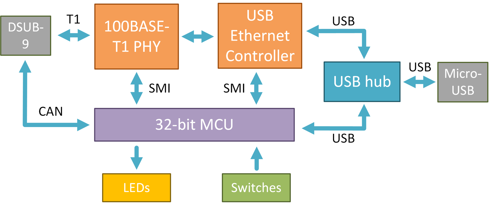
The interface establishes a point-to-point link between an unshielded twisted-pair IEEE 100BASE-T1 (IEEE 802.3bw) port and USB-LAN port and works as a Network Interface Card allowing the user to configure the network adapter’s parameters, such as IP address and mask. The converter features a DSUB9 (BroadR-Reach, CAN bus) and Micro-USB connector. The OABR channel’s Master/Slave configuration is selected by a switch button or programmatically.
100BASE-T1 USB Interface offers a possibility to access SMI registers of the 100BASE-T1 transceiver (PHY) via a CAN bus or a USB’s virtual serial port. This enables the user to evaluate signal strength, detect polarity of the T1 port, carry out a BroadR-Reach media test to diagnose cable errors, fine-tune the PHYs parameters, and generally to read and write the registers.
- 100BASE-T1 (IEEE 802.3bw) to USB-LAN Interface
- Acts as USB 2.0 Network Adapter Card
- Master / Slave configuration by on-board dip switches or programmatically
- USB powered
- 4 Status LEDs
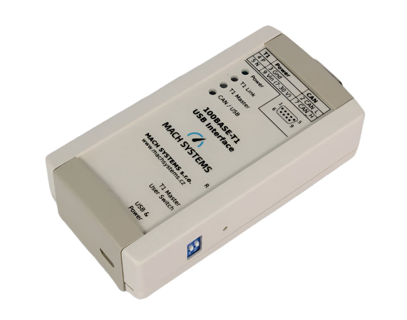
- DSUB9 connector for T1, RJ-45 connector for Ethernet
- Automatic polarity detection for OABR Slave
- Media test for T1 cable – can detect a shortage, cut-off and impedance mismatch
- Tabletop or DIN-rail mount
- Configuration and diagnostics over USB COM port (CDC) and CAN bus
| Property | Value |
|---|---|
| The information herein is subject to change without notice. | |
| Communication and Peripherals | |
| Channels | 2 CAN-HS (ISO 11898-2) with CAN FD support (ISO 11898-1:2015; CAN 2.0A/B, ISO CAN FD) 1 LIN bus (supports both master and slave; ISO 17987; LIN 2.2a) 1 RS-232 1 Virtual COM port (USB 2.0 CDC) |
| Inputs | 2 Analogue/digital inputs (0-5 V) |
| Outputs | 4 Digital outputs (PWM capable) DO1: HSD (5 V, max. 0.5 A) DO2, DO3: push-pull (5 V, max. 0.5 A) DO4: LSD (max. 40 V, 1.5 A) |
| Programming | Free-of-charge IDE and GNU C/C++ compiler (STM32CubeIDE) Programming examples available |
| Firmware update | over USB, CAN, RS-232, or ICSP (ST-LINK) |
| Debugging | ST-LINK SWD (a programming header needed) |
| Non-volatile memory | Internal 16 Kbit EEPROM External microSD card slot (a card is not part of delivery) |
| LEDs | 3 Dual-color LED 1 Power LED |
| Electrical | |
| Power | External 7 – 30 V DC with polarity protection over DSUB connector USB-powered over Micro-USB (not for LIN bus) |
| Consumption | 100 mA @ 12 V (approx. 1 W) Note: When no digital output (DO1-DO4) is being driven. |
| MCU | STM32G483 (Arm® 32-bit Cortex®-M4) with DSP and FPU; 170 MHz, 512 KB Flash, 128 KB SRAM |
| Transceivers | CAN-FD: MCP2562FD LIN: MCP2003B |
| Mechanical | |
| Connectors | 1 D-SUB9M 1 D-SUB9F 1 MicroSD slot 1 Micro-USB |
| Buttons and switches | 2 DIP switches 1 Tactile switch |
| Dimensions (L x W x H) | 108 x 54 x 30 mm |
| Weight | 85 g |
| Operating temperature | -20 to 70 °C |
| Protection | IP20 |
| Placement | Table (adhesive pads included) DIN-rail mount (clip sold separately) |
| Data Sheet |
| 100Base-T1 USB Interface Data Sheet |