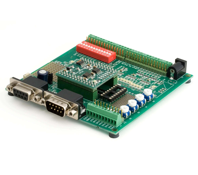
PCAN-MicroMod Evaluation Kit
Please note: The product has been discontinued. Please see the PCAN MicroMod FD series for new projects.
This MicroMod Evaluation Kit from PEAK provides the CAN developer with a complete set of hard- and software components to create a full-featured CAN I/O device. This Kit includes a PCAN-USB Adapter CAN interface, a MicroMod Evaluation Board, a MicroMod CPU Board, power adapter, CAN cable (3 ft.) and the PEAK Product DVD with MicroMod Configuration Software. The MicroMod CPU is a small (32 x 36 mm) module for OEM designs, it requires a single regulated 5 VDC power supply. The integrated firmware allows for simple configuration of the module with the FREE Windows configuration software. No embedded programming skills are required. The configuration data is sent to the module via the CAN bus. Up to 32 MicroMods can be integrated in a single CAN network. Each individual module can be addressed over the bus enabling to read, modify and store its configuration data.
SOFTWARE:
The included Windows software makes the following module configuration options available to the user: The digital input levels can send periodically or following a signal level transition (rising edge, falling edge or both transitions). Digital inputs can be logically connected (AND, OR, XOR, NAND, NOR, XNOR). The results are then displayed on the desired digital outputs and/or sent over the CAN bus. Analog values can be converted by Scale-value and Offset-value and then processed further. Adaptation of analog values is possible via characteristic curves. Direct conversion of analog inputs to CAN-IDs is supported. The rotary-switches (based on the rotary-encoder principle), which are standard in automotive applications, are supported directly.
Evaluation Board:
- Open-collector output driver for digital outputs and CMOS PWM outputs
- Protected digital inputs + LED
- 4 potentiometers for analog inputs
- Low pass and resistive divider for voltages > 5 V
- Serial interface for firmware updates
- Optional Low-speed CAN transceiver
- Dimensions: approx. 100 x 100 mm
- Part # IPEH-002082
MicroMod:
- Subminiature dimensions (32 x 36 mm)
- Fujitsu MB90-F497 CAN controller
- 8 x analog inputs, 10-bit, Vref 5V
- 8 x digital inputs
- 8 x digital outputs
- 4 x PWM/frequency outputs, range 1 Hz to 20 KHz
- Maximum of 32 MicroMods in one CAN network
- Configurable via software for Windows® 8,7/Vista/XP (32/64-bit)
- Part # IPEH-002080
Configuration software:
- Periodic and edge-triggered sending of CAN messages
- Logical linking of digital inputs
- Direct conversion from analog inputs to CAN IDs
- Analogue values can be processed using characteristic curves or hysteresis function
- Direct evaluation of rotary encoders
PCAN-USB Adapter:
- Interface in compact plastic casing
- Transfer rates up to 1 Mbit/s
- Compliant with CAN specifications 2.0A (11-bit ID) and 2.0B (29-bit ID)
- CAN bus connection via D-Sub, 9-pin (to CiA® 102)
- NXP SJA1000 CAN controller, 16 MHz clock frequency
- 82C251 CAN transceiver
- Hardware can be reset via software
- 5-Volts supply to the CAN connection can be connected through a solder jumper, e.g. for external transceiver
- Voltage supply through USB bus
- Non-optically isolated version
CAN Cable:
- PCAN Cable 2 with 120 Ohm terminating resistors
- Part # IPEK-003001
| Power Consumption | 6.4 – 12 V DC (with existing voltage regulator) For higher input voltages the use of an alternative voltage regulator or an integrated switch regulator is possible |
| Digital inputs | Count: 8 Level: TTL, Low-active Low-pass: 100 kΩ/4.7 nF Additional circuits: DIP switches |
| Frequency inputs | Count: 4 Level: TTL Low-pass: 100 kΩ/4.7 nF, enabled with solder jumpers JP13 - JP16 (delivery status: disabled) |
| Analog inputs | Count: 8 Input voltage: 0 - 5 V Input impedance: 6.5 kΩ (3.3 kΩ Evaluation Board + 3.2 kΩ MicroMod) Additional circuits: Potentiometers connectible for inputs Ain0 to Ain3 |
| Digital outputs | Count: 8 Type: Low-side switch, pull-up resistors 3.3 kΩ connectible Load: max. 350 mA |
| Frequency/PWM outputs | Count: 4 |
| CAN | Transmission standards: High-speed CAN ISO 11898-2 (Transceiver on MicroMod); Transceiver for Low-speed CAN ISO 11898-3 can be installed on Evaluation Board Termination: 120 Ω for High-speed CAN, can be connected with solder jumpers JP23/24 (delivery default status: not connected), implemented as split termination, (2 x 60 Ω and 10 nF against ground), 5.6 kΩ for Low-speed CAN lower termination resistance can be installed Connection: D-Sub 9-pin m, assignment according to specification CiA® 102 |
| Dimensions | 100 x 102 mm (W x L) |
| Weight | 88 g (without MicroMod) |
| Operating temperature | 0 - +85 °C (+32 - +185 °F) |
| Storage temperature | -40 - +100 °C (-40 - +212 °F) |
| Relative humidity | 15% - 90%, not condensing |
| PCAN-MicroMod Evaluation Kit manual |
| Manual in PDF format |
| PCAN-MicroMod package |
| The package includes the configuration software PCAN-MicroMod Configuration for Windows®, the latest PCAN-MicroMod and the CANopen® firmware, all files for development, and documentation |
| PCAN-MicroMod Configuration |
| PCAN-MicroMod Configuration software for Windows® 10, 8.1, 7 (32/64-bit) |


