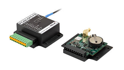
- NXP LPC4000 series microcontroller (ARM Cortex-M4)
- Receiver for navigation satellites u-blox MAX-7W (GPS, Galileo, GLONASS, QZSS, and SBAS)
- Bosch BMC050 electronic three-axis magnetic field sensor and three-axis accelerometer
- Gyroscope STMicroelectronics L3GD20
- High-speed CAN channel (ISO 11898-2) with bit rates from 40 kbit/s up to 1 Mbit/s
- Internal 2-kByte EEPROM
- microSD™ memory card slot
- Wake-up by CAN bus or by separate input
- 2 digital inputs (high-active)
- 1 digital output (low-side driver)
- LEDs for status signaling
- Connection via a 10-pole screw-terminal strip (Phoenix)
- Voltage supply from 8 to 30 V
- Extended operating temperature ranges from -40 to 85 °C (with exception of the button cell)
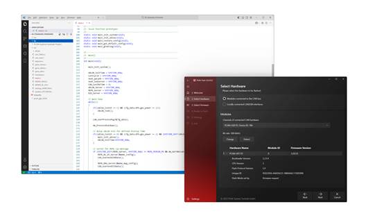
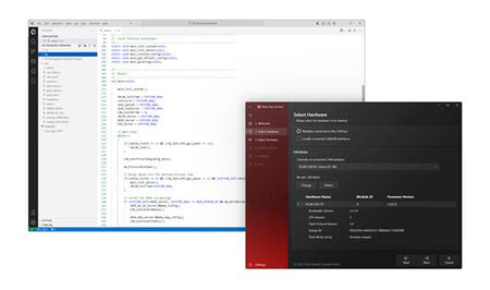
- New firmware can be loaded via CAN interface
- To transfer the firmware via CAN, a PEAK CAN interface is required
| Connectors | Screw terminal strip, 10-pin 3.5mm pitch (Phoenix Contact MC 1.5/10-ST-3.5 - order# 1840447) Antenna: sub-miniature-A (SMA); supply for antenna: 3.3V, max. 50 mA Memory card: internal microSD slot for cards up to 32GByte, types SD and SDHC |
| Power Supply | Supply voltage: +8 … +30 VDC Current consumption normal operation: 8V = 100mA, 12V = 60mA, 24V = 30mA, 30V=25mA Current consumption sleep mode: 60μA Button cell for RTC (and GNSS if required): 3 V, type CR2032; Note: Observe the operating temperature range for used button cell. |
| CAN Interface | Specification: High-speed CAN per ISO 11898-2, 2.0A (standard format) and 2.0B (extended format) Bit rates: 40 kBit/s...1 MBit/s Transceiver: NXP TJA1041T, wake-up capable Bus termination: None |
| Receiver for navigation satellites (GNSS): | Type: u-blox MAX-7W Receivable navigation systems: GPS, GLONASS, Galileo, QZSS, SBAS Connection to microcontroller: serial connection (UART2) with 9600 Baud 8N1 (default) Operation modes: continuous mode or power-saving mode Antenna type: active or passive Protective circuit antenna: monitoring of the antenna current on short circuit with message Maximum update rate of navigation data: 10 Hz Maximum number of satellites received at the same time: 56 Sensitivity: max. 161 dbm (tracking and navigation) Time to first position fix after cold start (TTFF): about 30 secs Accuracy of positioning values: GPS = 2.5m; GPS with SBAS = 2m, GLONASS = 4m Supply for active antenna: 3.3V @ 50mA (max), switchable |
| Antenna for satellite reception | Type: taoglas Ulysses AA.162 Center frequency range: 1574 - 1610 MHz Operating temperature range: -40 - +85 °C (-40 - +185 °F) Size: 40 x 38 x 10 mm Cable length: about 3 m Weight: 59 g Special feature: Integrated magnet for mounting |
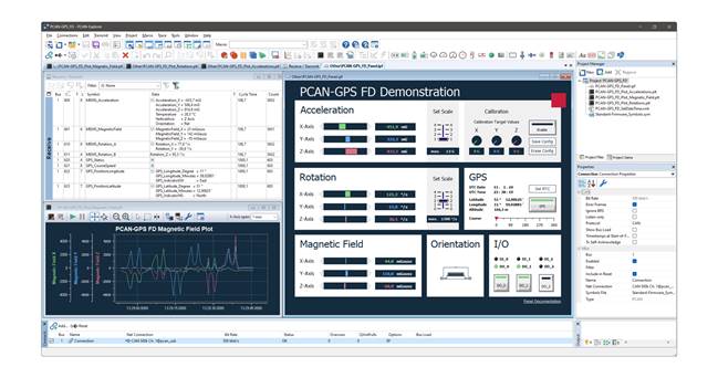
| Gyroscope | Type: STMicroelectronics L3GD20 Connection to microcontroller: SPI Axes: roll (X), pitch (Y), yaw (Z) Measuring ranges: ±250, ±500, ±2000 dps (degrees per second) Data format: 16 bits, two's complement Output data rate (ODR): 95 Hz, 190 Hz, 380 Hz, 760 Hz Filter possibilities: Configurable high-pass and low-pass Power saving modes: Sleep (2 mA), Power-down (5 μA) |
| Acceleration and magnetic field sensor | Type: Bosch Sensortec BMC050 Connection to microcontroller: SPI |
| Accelerometer | Measuring ranges: ±2/±4/±8/±16 G Data format: 10 bits, two's complement Filter possibilities: Low-pass with 1 kHz - 8 Hz bandwidth Operating modes: Power off, Normal, Suspend, Low-Power Correction options: Offset compensation |
| Magnetic field sensor | Sensitivity: X, Y: ±1000 μT; Z: ±2500 μT Data format: X, Y: 13 bits, two's complement; Z: 15 bits, two's complement Output data rate (ODR): 2 - 30 measurements per second Operating modes: Power off, Suspend, Sleep, Active |
| Digital inputs | Count: 2 (terminals 6 and 10) Switch type: High-active (internal pull-down), inverting Max. input frequency: 3 kHz Switching thresholds: High: Uin ≥ 3 V | Low: Uin ≤ 2.2 V Internal resistance: 133 kΩ |
| Digital output | Count: 1 (terminal 5) Type: Low-side driver Max. voltage: 30V Max. current: 0.5A Short-circuit current: 1.5A |
| Microcontroller | Type: NXP LPC4074 Clock frequency quartz: 12MHz Clock frequency internally: max. 120 MHz (programmable by PLL) |
| Dimensions | 45 x 68 x 26 mm (without SMA connector), see dimensional drawing in the User's Manual - attachment B |
| Weight | Circuit board: 33 g (incl. button cell and mating connector) Casing: 17 g |
| Operating temperature | -40 … +85 °C (-40 … +185 °F); (except button cell) Button cell (typical): -20 - +60 °C (-5 to +140 °F) |
| Storage temperature | -40 … +85 °C (-40 … +185 °F); (except button cell) Button cell (typical): -40 - +70 °C (-40 to +160 °F) |
| Relative humidity | 15% to 90% (non-condensing) |
| EMI/Protection | EN 61326-1:2013-07 EC directive 2004/108/EG IP20 (DIN EN 60529) |
| Certifications | CE |
| PCAN-GPS FD manual |
| User's Guide PCAN-GPS FD |
| PCAN-GPS FD manual - Antenna Appendix |
| Antenna Specifications Datasheet |
| PCAN-GPS FD manual - GNSS Appendix |
| GNSS Specifications Datasheet |
| PCAN-GPS FD manual - Gyroscope Appendix |
| Gyroscope Specifications Datasheet |
| PCAN-GPS FD manual - Magnetic Field Sensor Appendix |
| BMC050 Electronic Compass Datasheet |
| PCAN-GPS FD manual - Microcontroller Appendix |
| LPC408x/407x User Manual |
| PCAN-GPS FD Package |
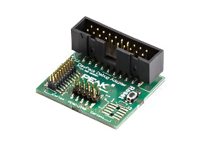
| The development package includes all files for custom firmware development: Yagarto GNU ARM toolchain, Flash program, library and programming examples |

