
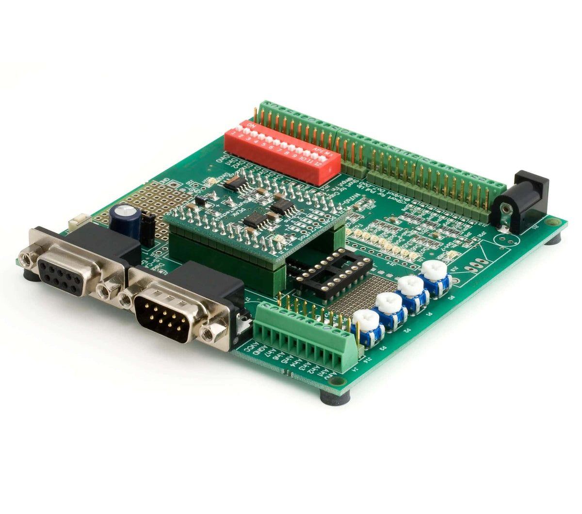

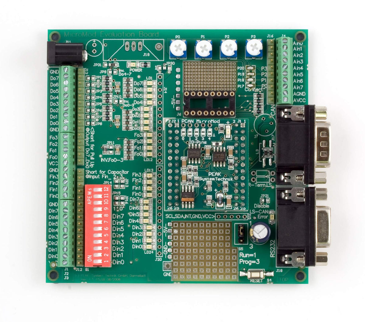


Evaluation Board:
- Open-collector output driver for digital outputs and CMOS PWM outputs
- Protected digital inputs + LED
- 4 potentiometers for analog inputs
- Low pass and resistive divider for voltages > 5 V
- Serial interface for firmware updates
- Optional Low-speed CAN transceiver
- Dimensions: approx. 100 x 100 mm
- Part # IPEH-002082
MicroMod:
- Subminiature dimensions (32 x 36 mm)
- Fujitsu MB90-F497 CAN controller
- 8 x analog inputs, 10-bit, Vref 5V
- 8 x digital inputs
- 8 x digital outputs
- 4 x PWM/frequency outputs, range 1 Hz to 20 KHz
- Maximum of 32 MicroMods in one CAN network
- Configurable via software for Windows® 8,7/Vista/XP (32/64-bit)
- Part # IPEH-002080
Configuration software:
- Periodic and edge-triggered sending of CAN messages
- Logical linking of digital inputs
- Direct conversion from analog inputs to CAN IDs
- Analogue values can be processed using characteristic curves or hysteresis function
- Direct evaluation of rotary encoders
PCAN-USB Adapter:
- Interface in compact plastic casing
- Transfer rates up to 1 Mbit/s
- Compliant with CAN specifications 2.0A (11-bit ID) and 2.0B (29-bit ID)
- CAN bus connection via D-Sub, 9-pin (to CiA® 102)
- NXP SJA1000 CAN controller, 16 MHz clock frequency
- 82C251 CAN transceiver
- Hardware can be reset via software
- 5-Volts supply to the CAN connection can be connected through a solder jumper, e.g. for external transceiver
- Voltage supply through USB bus
- Non-optically isolated version
CAN Cable:
- PCAN Cable 2 with 120 Ohm terminating resistors
- Part # IPEK-003001
| Power Consumption | 6.4 – 12 V DC (with existing voltage regulator) For higher input voltages the use of an alternative voltage regulator or an integrated switch regulator is possible |
| Digital inputs | Count: 8 Level: TTL, Low-active Low-pass: 100 kΩ/4.7 nF Additional circuits: DIP switches |
| Frequency inputs | Count: 4 Level: TTL Low-pass: 100 kΩ/4.7 nF, enabled with solder jumpers JP13 - JP16 (delivery status: disabled) |
| Analog inputs | Count: 8 Input voltage: 0 - 5 V Input impedance: 6.5 kΩ (3.3 kΩ Evaluation Board + 3.2 kΩ MicroMod) Additional circuits: Potentiometers connectible for inputs Ain0 to Ain3 |
| Digital outputs | Count: 8 Type: Low-side switch, pull-up resistors 3.3 kΩ connectible Load: max. 350 mA |
| Frequency/PWM outputs | Count: 4 |
| CAN | Transmission standards: High-speed CAN ISO 11898-2 (Transceiver on MicroMod); Transceiver for Low-speed CAN ISO 11898-3 can be installed on Evaluation Board Termination: 120 Ω for High-speed CAN, can be connected with solder jumpers JP23/24 (delivery default status: not connected), implemented as split termination, (2 x 60 Ω and 10 nF against ground), 5.6 kΩ for Low-speed CAN lower termination resistance can be installed Connection: D-Sub 9-pin m, assignment according to specification CiA® 102 |
| Dimensions | 100 x 102 mm (W x L) |
| Weight | 88 g (without MicroMod) |
| Operating temperature | 0 - +85 °C (+32 - +185 °F) |
| Storage temperature | -40 - +100 °C (-40 - +212 °F) |
| Relative humidity | 15% - 90%, not condensing |
| PCAN-MicroMod Evaluation Kit manual |
| Manual in PDF format |
| PCAN-MicroMod package |
| The package includes the configuration software PCAN-MicroMod Configuration for Windows®, the latest PCAN-MicroMod and the CANopen® firmware, all files for development, and documentation |
| PCAN-MicroMod Configuration |
| PCAN-MicroMod Configuration software for Windows® 10, 8.1, 7 (32/64-bit) |